General Help Guides
Getting Started as Team
- Setting up your Team Name and Logo
- In the drop-down menu on the upper-right, press your user icon —> Admin —> Teams
- Change your Team Name
- Upload your logo
Inviting Team Members
In the drop-down menu on the upper-right, press your user icon —> Admin —> Teams
Choose Admin for the full administrative panel
You can add and remove multiple administrators to your team.
Administrators can add and remove teammates.
Teammates that are removed have their project data stay with the account.
Read only team-members can be checked on or off here.
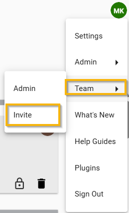
Team Admin
You can also invite new members from the team admin tab in the same drop down menu.
The team admin page shows how many active users you have on your team.
From this page you can also remove users by clicking on the trashcan beside their name. This will not delete any data or models they have worked on.
Messaging within LightStanza
You can tag team members to get feedback about your work.
You can tag the client to see what they think of the work you have done and if there are any changes that need to be made.
In order to tag people just hit the + button on your keyboard and type in the email of the recipient.
LightStanza Support
-
You can also tag LightStanza support in you designs to get help or ask a question.
-
In order to tag support type +support@lightstanza.com in the comment section in the activity bar or in a report.
-
LightStanza support will get back to you and help resolve issues and answer questions.
Modeling Concepts for LightStanza
This guide is meant to help you organize your 3D models and streamline your workflow to make it easy to work with your product later. In order to ensure an efficient and organized modeling process, you will also need to be familiar with how to build your model flexibly with materials and layers.
We recommend organizing your model by layer or material to allow for more flexibility later in app.lightstanza.com. For example, you will have windows in your project, but they may not all perform the same function. In the illustration below, there is a row of windows with an accompanying row of daylight windows. The bottom windows will be standard, but you want the daylight windows to have a special type of daylight glazing. Putting the daylight windows on their own layer will make it easy to assign each window type its specific properties.
Materials
One way to organize your model is through material assignment. Material assignments should be used when you want to change the lighting characteristics of a polygon. For example, you can change something from glass to opaque or vice versa, convert a polygon to a BSDF file, convert to a translucent plastic, etc.
Each part of the model that will have different light behavior should be a unique material. Initial settings are taken into account during the upload process (materials with less than 100% opacity are assumed to be glass), but it does not matter which material you assign when you are working in SketchUp since everything can and should be changed later on LightStanza.com. See the illustrations below for details.
* Note on SketchUp Textures: LightStanza initially analyzes materials based on RGB values and opacity. SketchUp Textures are not supported by LightStanza since they are not physically accurate descriptions of materials (like .bsdf files are). If you have SketchUp Textures in your model, be sure to assign a different material either in SketchUp or on app.lightstanza.com.
If you are using Revit, your glass and opaque materials will go through a conversion when uploaded to LightStanza. Below are the conversion formats for the two material types:
- Glass Materials:
LightStanza reads the red, green, and blue transmission values (tr, tg, tb) directly from the Revit material, and converts them to a simple VT value (note that the tr, tg, and tb values are passed directly to Radiance):
T = tr * 0.2126 + tg * 0.7152 + tb * 0.0722
VT = (100 * 0.5 * (-√(2.45 × 10104 * T2) + 6.57 × 1097) – 1.57 × 1052 * T) / (3.10 × 1049 * T2 – 1.71 × 1052)
- Opaque Materials:
LightStanza reads the red, green, and blue reflectance values (R, G, B) directly from the Revit material, and converts them to a simple, combined reflectance value:
Reflectance = 100 * (R * 0.2126 + G * 0.7152 + B * 0.0722)
Layers
Note: When importing a CAD file, LightStanza maintains the layer structure from the imported DWG. For Revit projects, layers are created based on Revit Categories.
Another strategy you should use for model organization is layers. Layers should be used to organize and control geometry. Things like furniture, window blinds, and overhangs will typically be on their own layers. When furniture is all on a separate “Furniture” layer, you can turn the layer on and off on app.lightstanza.com. This is useful because it is interesting to see the furniture in renderings, but it should be turned off if you are only interested in getting quick quantitative results.
The next three illustrations show how to use layers and materials.
Elevation A Shows a set of daylight windows with daylight film and a set of view windows. In this elevation we see three unique materials. The facade is assigned material “Wall”, the windows with daylight film are assigned material “Daylight Window”, and the view windows are assigned material “View Window”. Name the materials something that you can easily identify on LightStanza.com when you assign them specific properties.

Elevation A
In Elevation B we see two layers and two materials. The facade and windows represent Layer 1, and the overhang is Layer 2. The facade and overhang are the material “wall” and the windows are material “View Window”. The overhang should be modeled on its own layer, which can be turned on or off on LightStanza.com. That way, you will be able to see how the room is lit with and without the overhang and assess its effectiveness. You can also add other overhang layers to account for vertical fins and turn them on individually or in conjunction with the horizontal overhang layer.
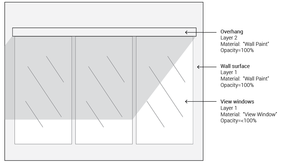
Elevation B
In Elevation C there are two layers and three materials. There is one set of daylight windows with daylight film and an overhang. The two sets of windows will have different material properties assigned to them.
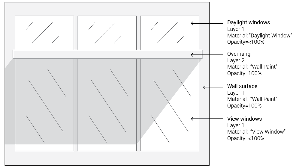
Elevation C
You can also assign material properties to the glazing and blinds or shades, as well as define the covering (blind/shade) behavior after you upload your model to app.lightstanza.com.
Modeling the Ground Plane
It is essential to always model your ground plane. Without modeling a ground plane, your simulations will not accurately depict light bouncing from the ground into your space. Below are ground plane guidelines to follow.
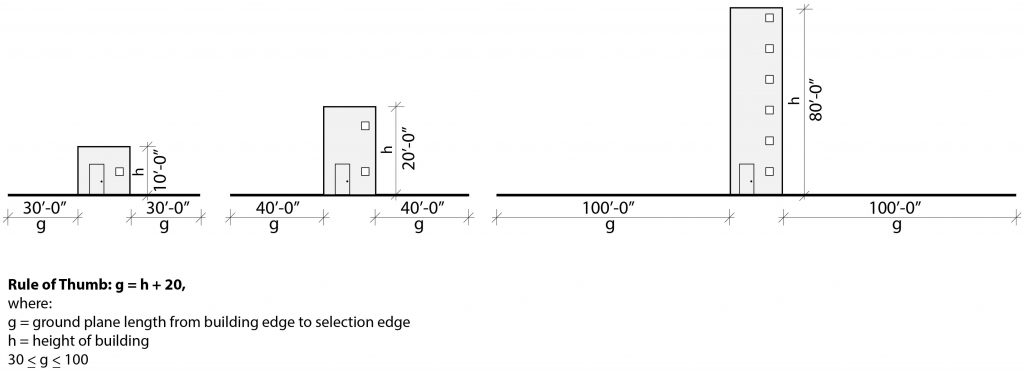
Wall Thickness and Detail
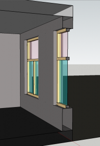
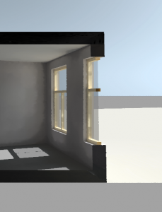
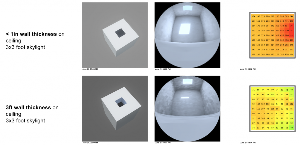
The thickness of walls in buildings affects the way light enters the space. For accuracy in light analysis as required by LEED and WELL standards, construct your SketchUp model with accurate wall thickness, but windows as only a single pane. You will assign all complex lighting functions and characteristics for the window on LightStanza.com. Multi-plane glass, blinds, and daylight film are all examples of complex lighting functions that you will assign on LightStanza.com. For example, even if the window will be triple-pane glass, model it in SketchUp as single plane.
Model Units/Scale
Make sure to double check the units (e.g. sizes/lengths) within your model before uploading. This will ensure that the model is scaled correctly. If the model is not scaled properly in your modeling software (i.e. too big/small), daylighting results may be incorrect.
Floors
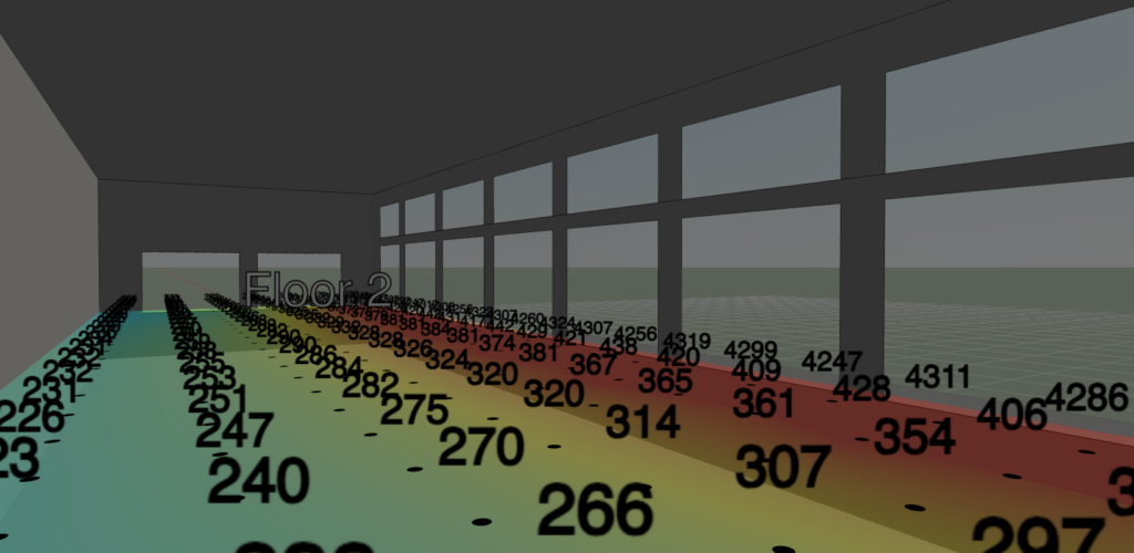
Floors in LightStanza are for display purposes only and do not impact simulation results. They are intended merely as a convenience for organizing and viewing data. Floors are generated automatically and currently cannot be changed after they are created. Please note that the floor assignments when viewing grids in the Illuminance Grids Panel and when viewing simulation results may not always correspond exactly.
The floors displayed in the Illuminance Grids panel are assigned based on grid height and take both user-defined and automatically-generated grids into account. Grids are sorted by height, and the lowest grid is assigned to Floor 1. The next-highest grid is then checked, and if its height is within 1m of the first grid on Floor 1, this grid is also assigned to Floor 1. Otherwise, a new floor (Floor 2) is created to which the grid is assigned. This process is repeated until all grids have been assigned to a floor.
The floors displayed on a simulation report only take grids that are active for that simulation into account. During simulation, groups of coplanar grids are created and then sorted by the height of the center point of the group to create floors. If grids are coplanar but point in opposite directions (e.g. some face upward while others face downward), they will be assigned to separate floors. Grids that are not horizontal (e.g. grids measuring vertical illuminance on a wall) will be assigned to floors named e.g. “Section 1”, “Section 2”, etc.
Preparing your Model for Generating Results in LightStanza
This section will teach you how to use your 3D modeling tool to prepare for generating results in LightStanza. Then it will explain how to kick off simulations from the activity bar using the left toolbar simulation settings.
Current Caveats of Different 3D Modeling Software
- SketchUp models must first be exported to the Collada format. Then drag-and-drop the Collada file into LightStanza.
- To ensure model translation accuracy, uploading Revit files requires the use of our free LightStanza Plugin. The plugin is capable of exporting native Revit elements, but not yet able to include geometry from imported formats such as a linked DWG file or 3D CAD files. However, it is possible to create a Revit family with imported CAD geometry. More information on this technique can be found in our Revit Export guide.
- Rhino files must be converted into Collada (.dae) format before loading into LightStanza. You can do this from the “File -> Save As” menu in Rhino. We are currently unable to retain layer information when loading Rhino files into LightStanza, and apologize for the inconvenience.
- There are different steps for manually uploading illuminance grids from SketchUp, Revit, and Rhino. To learn these different workflows, visit the Create an Illuminance Grid section below.
- There are different steps for uploading windows from SketchUp, Revit, and Rhino. To learn these different workflows, visit the Create Windows section below.
- LightStanza does not support different materials applied to the front and back sides of SketchUp objects. For best performance, apply the same material to both sides of an object.
- LightStanza does not currently support importing textures from external modeling software. Materials with textures applied will have these textures removed when importing into LightStanza.
How to Create an Illuminance Grid
An Illuminance Grid is a planar system of points that collects light for analysis in your model. These can be horizontal or vertical. To create an Illuminance Grid in your modeling program, you can name a material “LSGrid” (SketchUp), use the LightStanza plugin (Revit), or change the color of a material to yellow (Rhino). Below are detailed instructions for each modeling program.
Please note that LightStanza automatically creates Illuminance grids when you upload your 3D model. These will be placed 30 inches (762 mm) above the floor. You still have the option to manually create user-defined illuminance grids, which are helpful for precise separation of spaces and for measuring light vertically.
In SketchUp
- Draw a polygon where you want your Illuminance Grid to be. A helpful tip is to make a copy of the floor and move it up to workplane height (30″ or 760mm above the floor), or to the height at which you wish to measure light. Illuminance grids can be standard horizontal, vertical, or diagonal.
- Choose the planes in your model that you would like to measure daylight on and rename the corresponding material to include the text “LSGrid” (this is not case sensitive).* It is recommended that you assign the grid material to both sides of the polygon. Assigning only the back face material will not create an Illuminance Grid in SketchUp if the front face is not also assigned.
- For example, if your material is “Office 323” and you rename it to “LSGrid Office 323”, the polygon will be added to your list of grids. Additional text beyond “LSGrid” will be used as its name online, such as naming ‘Office 323’ and ‘Office 345’ the following material names can be used:
- LSGrid Office 323
- lsGRID Office 345
- LSGrid Kitchen
- For example, if your material is “Office 323” and you rename it to “LSGrid Office 323”, the polygon will be added to your list of grids. Additional text beyond “LSGrid” will be used as its name online, such as naming ‘Office 323’ and ‘Office 345’ the following material names can be used:
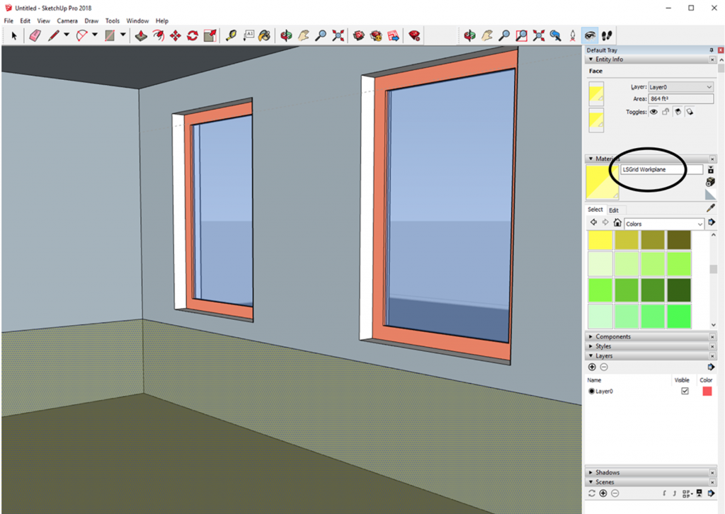
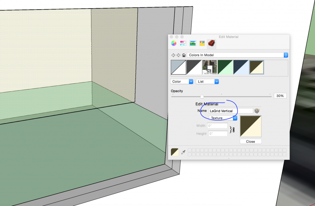
- Once the desired materials have been renamed, save your model by clicking “save As” > “SketchUp (*.skp)”.
- Export your model to LightStanza using the LightStanza Extension. If you are unable to use extensions with your version of SketchUp, first export it as a Collada file (File -> Export -> 3D model) and then drag-and-drop the .dae file or use the “+” button in the top menu.
In Rhino
- Draw a planar surface where you want your Illuminance Grid to be. A helpful tip is to make a copy of the floor and move it up to workplane height (30″ or 760mm above the floor), or to the height at which you wish to measure light.
- Illuminance grids can be standard horizontal, vertical, or diagonal.
- Set the name of the material assigned to this surface to include the string “lsgrid” or “ls_grid”. For example, with a material name of “lsgrid Office 1”, the grid in LightStanza will be named “Office 1”. Note that you can put all your grids on the same Rhino layer, and assign a material to that layer following this rule – however, note that if done this way all grids will have the same name in LS.
- Export your model in Collada (.dae) format (you can do this via the “Save As” menu in Rhino), and drag-and-drop the .dae file into LightStanza, or use the “New Design -> Import File” option from the folders page. The illuminance grids you made will appear under Imported Grids inside of the Illuminance Grids tab in the left toolbar.
Creating New Calculation Grids in LightStanza
Click the “Add +” button on the Calculation Grids panel. Choose the desired option, then click anywhere in the 3D or 2D model to place the calculation grid.
Placement Options
- From Surface — Attaches calculation points to any planar surface.
- Square Stamp (10′ x 10′) — Places a 10 foot square calculation grid to the project (LEED Recommendation).
- Rectangle — Places a rectangular calculation grid by setting the lower-left and upper-right corners.
- Polygon — Places a calculation grid by setting the nodes of the polygon.
- Egress (line) — Places calculation points along a line for egress paths or property lines.
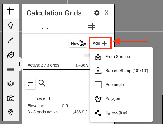
To make adjustments to the calculation grid such as height, spacing, or orientation, right click and select “Edit” in either the 2D or 3D LightStanza mode.
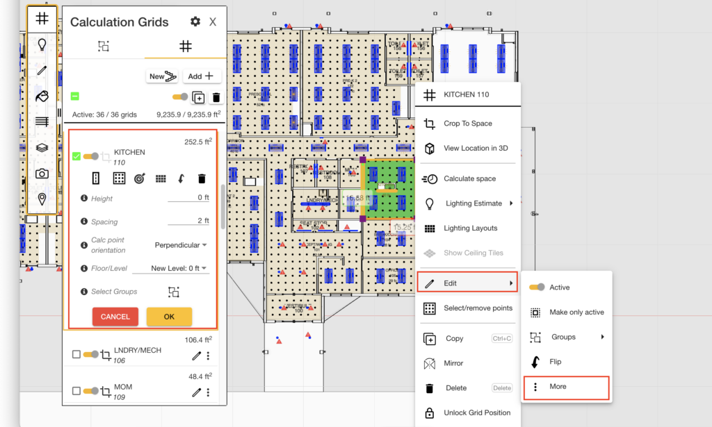
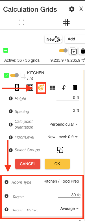
Adjust the room type and target illuminance value for each new grid that is created by selecting the target icon.
Automatic Grids
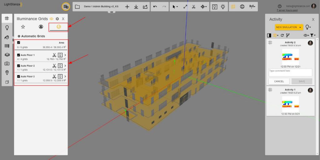
LightStanza will automatically generate illuminance grids for SketchUp or Rhino models that are imported into the app.
The automatic grids are accessed on the Illuminance Grids panel within the LightStanza app.
Using LightStanza on an iPad
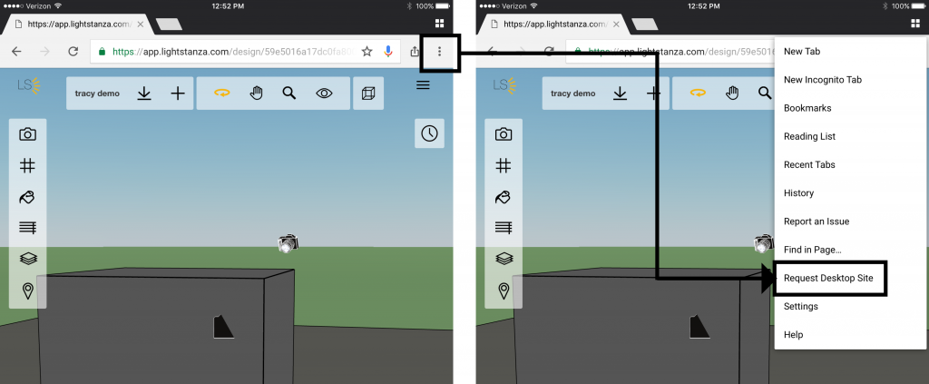
If you are using LightStanza on an iPad, make sure to “Request Desktop Site” for easier-to-use 3D controls. You can do this in both Safari and Google Chrome:
- Using Safari, hold your finger/cursor down on the “Refresh” button next to the address bar. The option to “Request Desktop Site” will pop up below for you to click on.
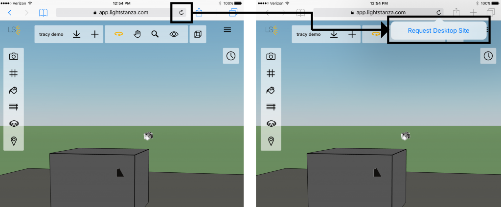
- Using Safari, hold your finger/cursor down on the “Refresh” button next to the address bar. The option to “Request Desktop Site” will pop up below for you to click on.
- Using Google Chrome, click on the top right menu button and select “Request Desktop Site” from the dropdown menu options.
Editing your Model in LightStanza
This section will cover the different elements of the left toolbar in the LightStanza 3D viewer. Making changes in this panel will affect your model settings. Model settings have to do with the physical components of the 3D model.
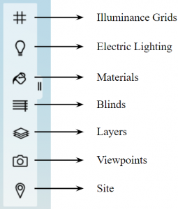
Viewpoints
Viewpoints List – In the Viewpoints tab, there may be a list of viewpoints that were uploaded from your CAD tool. You can also create new viewpoints in LightStanza by navigating the 3D viewer to the desired location and angle and clicking the ‘+’ sign next to Viewpoints. Clicking on the viewpoints in the list will move you to the corresponding camera location and angle in the 3D viewer. These are not necessary to make renderings (renderings can be made in LightStanza from on-the-fly viewpoints. In other words, if you start a new rendering, it basically takes a snapshot at the current location and angle of your 3D viewer).
Illuminance Grids
Illuminance Grids List – Your Illuminance Grids tab is split into three sections: Favorite Grids, User-defined Grids, and Automatic Grids. User-defined Grids are a list of illuminance grids that were assigned in your 3D modeling program. To learn how to populate this list, see the Illuminance Grids Section above. Automatic grids are automatically added to your model when you upload it to LightStanza. LightStanza does its best to put these at the workplane on each floor of your model, but if you need space-by-space or custom grid measurements, it is best to create them in your 3D modeling tool (explained in the Illuminance Grids section above). Favorite Grids are those you mark with the “Star” icon. This tool is great creating scenes of grids for reference. You can do a few things with the grids listed on this panel:
- Hovering over individual grids will highlight them in the 3D viewer for reference.
- Selecting and deselecting the check-boxes on each illuminance grid will turn them on and off for viewing and for simulations (for example, if you would like to exclude unoccupied spaces from your LEED v4 Daylight Credit Report, deselect those spaces in the Illuminance Grids tab so that they will not be included in the calculation).
- Clicking the “Flip Grid” button (click the pencil icon to view) next to each grid will change the side that light is measured on. Here is how to do this:
- First you will need to determine the direction your Illuminance Grids are facing. In the LightStanza 3D viewer, locate the illuminance grids in your model. The orange side of the illuminance grid is the side that will measure light. The blue side will not measure light.
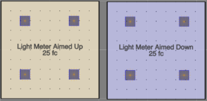
The color of the calculation grid indicates orientation. 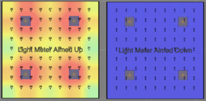
On the left, all illuminance from luminaires is registered. On the right, only light reflected from floor is registered. - If any of your Illuminance Grids are facing the wrong direction (i.e. the orange side of the polygon is not facing the side you want to measure light on), you will need to flip them in LightStanza. To do this, find the grid that needs flipped in the left toolbar Illuminance Grids panel. When hovering over the individual grids, you will see a pencil icon. Click it for access to the “Flip Grid” icon. Click this icon and it will change which side of your Illuminance Grid daylight gets measured on.
- First you will need to determine the direction your Illuminance Grids are facing. In the LightStanza 3D viewer, locate the illuminance grids in your model. The orange side of the illuminance grid is the side that will measure light. The blue side will not measure light.
- The light bulb icon associates a recommended light level from the IES handbook with the specific space. If importing a model from Revit, LightStanza will attribute a “Room Type” to that grid based on the Room name in the model. This “Room Type” will generate a target illuminance level per the IES recommended values as well as allow for definition of that level as an average, max or min value.
- The “Crop to Space” button allows you to reduce the model to that specific illuminance grid.
- Under “User-Defined Grids” or “Favorite Grids” you can create new illuminance grids in the LightStanza model. These grids may be adjusted in the same ways as those that were automatically defined in the model.
Materials
The Materials panel allows you to edit the materials in your model, along with their properties. This panel is separated into three categories – materials that are in your design, manufactured products (Product Library), and the generic materials.
- In Design – This list will show the materials that are in your design. From here, you can edit properties, select all, apply materials in your 3D model using the paint bucket tool, delete unwanted materials from your design, and save materials to your material library.
- Edit Properties – You can edit properties of your materials in two different formats – simple or “Radiance Format”. To turn Radiance Format on, click “View” at the top right of the material toolbar, and then click “Radiance Format”. Repeat this step to go back to simple mode. Each mode has different customizable properties.
- Please note that Dynamic Glass does not have editable properties since it has multiple tint states. Below is a list of these tint states.
- 3-tint:
- <15,000 lx: 0.6VT
- 15,000 lx – 50,000 lx: 0.15VT
- >50,000 lx: 0.01VT
- 4-tint:
- <15,000 lx: 0.58VT
- 15,000 lx – 30,000 lx: 0.4VT
- 30,000 lx – 50,000 lx: 0.06VT
- >50,000 lx: 0.01VT
* These are the illuminance levels measured at the center of each window group with dynamic glass.
- Product Library – This is a list of manufactured products separated by manufacturer name. To use these in your design, click on the desired product and it will be moved into the “In Design” library where you can use the paint bucket to apply it to polygons in your model. Information about modeling skylights can be found here, and information about modeling tubular daylight devices can be found here.
- Generic Materials – This is a list of generic materials. To edit or use these in your model, simply click on a material, and it will move into the “In Design” library where you can use the paint bucket to apply it to polygons in your model.
Navigating the 3D Viewer
This section will teach you how to navigate the 3D viewer in LightStanza. The controls mentioned here are in the top toolbar. Buttons and references will hide and show depending on the type of data that is showing in the 3D viewer.

- Go to parent folder – This button will bring you to the folder that contains the design you are in.
- Design Name – This is the name of your design, which can be edited when clicking on it.
- Copy Design – Make a copy of your design from its current state (including scope boxes) or copy the design with a new background.
- Download your Model – After uploading your model, a download button will appear. This will allow you to download the model that you originally uploaded to LightStanza as a file on your computer.
- New Design – This button allows you to add a model to your design. If there is already a 3D model in your design, this will replace it. You have the option to upload a SketchUp, Revit, or Rhino file. If you do not want to upload your own model, you can choose a sample model from the sample model library.
- Share your design – This button allows you to share your design in the exact state that it is in with team members and non-LightStanza users.
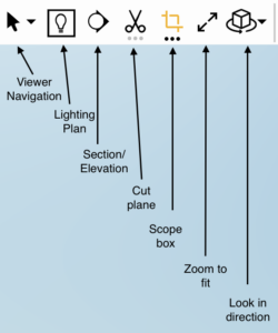
- Viewer Navigation (click to drop down all options)
- Select – This mode will allow you to select model elements.
- Orbit – This mode will allow you to rotate the 3D canvas around a point.
- Look Around – In this mode, you can turn the camera at a fixed point.
- Pan – This mode moves the 3D viewer without any rotation.
- Zoom – This mode will allow you to zoom in and out on the 3D viewer.
- Lighting Plan – Use this button to toggle between plan and 3D view modes.
- Section/Elevation – Use this button to draw a vertical cutting plane in the viewer. Press the space bar to flip the Section View’s direction. To create an elevation view, draw the cutting plane outside of the building.
- Cut plane – Use this button to apply a horizontal cutting plane to view inside your model. Does not affect calculation results. By clicking this icon you can cut into your model to view results more easily. When you click the “Cut plane” icon, you can adjust the cut location using the text input box to the right. You can also change where the section cut begins (ground or camera). Ground is the default, but can be changed by selecting ground to the right of the text input box.
- Scope box – Use this button to toggle the scope box on or off. Note: Adjusting the scope box can affect calculation results. When enabled, only elements within the scope box are considered for analysis.
- Zoom to Fit – Pushing this button will bring your model into view and fit it to the screen width.
- Look in direction
- Look North – Clicking this button will adjust the camera to be looking in the North direction.
- Look East – Clicking this button will adjust the camera to be looking in the East direction.
- Look South – Clicking this button will adjust the camera to be looking in the South direction.
- Look West – Clicking this button will adjust the camera to be looking in the West direction.
- Look Up – Clicking this button will adjust the camera to be looking directly up.
- Look Down – Clicking this button will adjust the camera to be looking directly down.
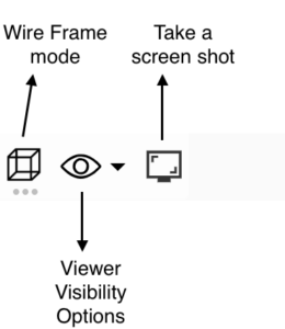
- Wireframe Mode – When clicking this button, you are able to make all opaque surfaces clear in your 3D model. This allows you to clearly view your results in the 3D viewer without any polygons in the way.
- Viewer Visibility Options (click to drop down all options).
- Calculation Grids
- Toggle visibility of the orange/blue calculation planes.
- Toggle calc point visibility.
- Toggle labels / adjust font size.
- Toggle illuminance estimates (average for space calculated via the lumen method).
- Luminaires
- Toggle photometric webs.
- Toggle luminous/IES dimensions
- Toggle aiming lines.
- Toggle warning signs.
- Toggle labels
- Adjust font scale.
- Toggle type label mark.
- Toggle mounting height label.
- Toggle fixture number.
- Show/Hide Sensors – These two options allow you to turn sensors for dynamic glass and blinds as well as illuminance sensors on/off. The amount of daylight that hits these sensors controls the way the blinds and dynamic glass operate.
- Show/Hide World Elements – Click this button to show/hide elements in the viewer that are not part of the model (the sky, ground, Sun Path, and compass rose). This is particularly useful when taking screenshots for reports and presentations.
- Calculation Grids
- Take a screen shot – Click this button to take a screen shot of the model viewer (excludes toolbars/panels). Image will be copied to clipboard and saved to downloads.
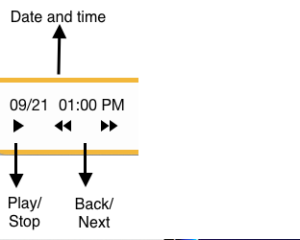
- Animate Results – Animation controls include play, stop, back, next, and the date/time for reference. These will only appear when an animation is open in the 3D viewer.
- Date/Time – When renderings or point-in-time illuminance grids are in the 3D viewer, there should always be a date and time for reference in the top toolbar. This is the date and time that the rendering or illuminance grid data represents. When viewing LEED v4 Option 2 or LEED 2009 results in the 3D viewer, this is section will either say 09:00 AM or 03:00 PM.


- Average/Compliance/Annual Score – When Point-in-time Illuminance Grids, Annual Illuminance Grids, or LEED Scorecard results are in the 3D viewer, this section will show a value and a corresponding legend. These numbers represent all of the grids that are currently showing data in the 3D viewer.
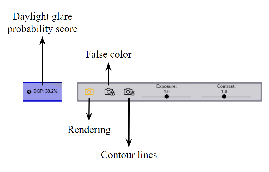
- Rendering Controls – When opening a rendering, a new set of rendering-specific elements are added to the top toolbar:
- Daylight Glare Probability (DGP) – This reference will only appear when you have opened a hemispheric rendering. This percentage represents the probability that a person is disturbed by glare at this specific viewpoint.
- Camera Tools – These three buttons allow you to switch between basic rendering mode, false color mode, and contour lines mode. The rightmost slider controls will change depending on which mode you are in.
- Exposure – You can manually adjust the exposure of your renderings in order to increase or decrease the amount of light per unit area. LightStanza uses Reinhard tone mapping for adjusting exposure.
- Contrast – Adjusting the contrast of your image will increase or decrease the difference between light and dark in your renderings.
- False Color – In the 3D viewer, you have the option to view your renderings in False Color mode for a more quantitative view of your images.
- Luminance Bounds – Changing your luminance sets what luminance values each color in your image represents. Adjust this to focus on very bright or very dark areas.
- Log Scale – Adjusting your log scale sets scaling of your false color heat map.
- Contour Lines – This is another way to look at your false color rendering. Contour lines trace the different luminance thresholds in your rendering, using the false color legend.
- Line Spacing – Changing your line spacing sets the density of the contour lines in your image.
